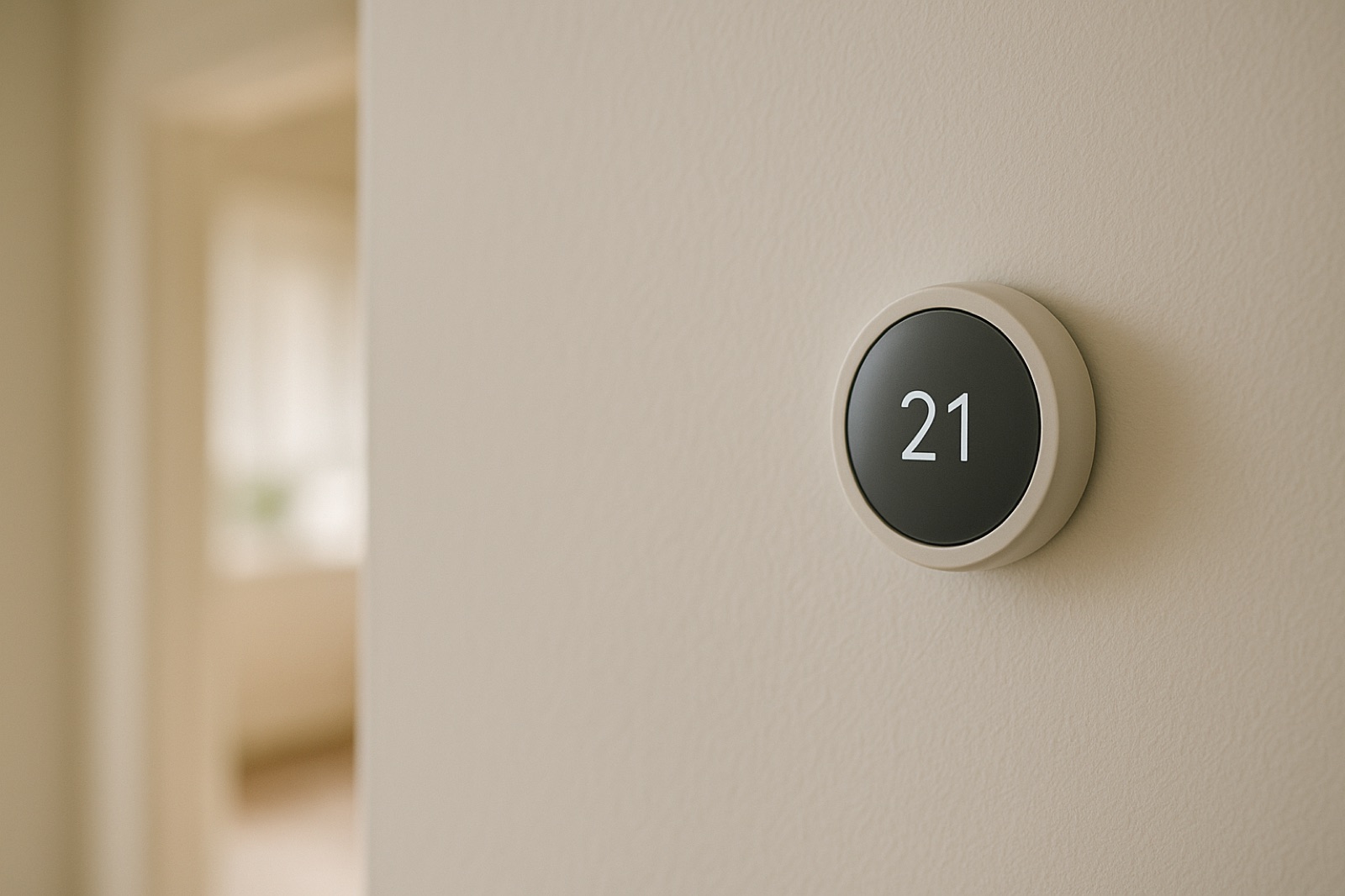
A thermostat may be the smallest piece of equipment in the HVAC system, but replacing one is not always a small job. That becomes especially clear when the wall control operates more than a basic furnace and air conditioner. Heat pump stages, auxiliary heat, whole-house humidifiers, dehumidifiers, ventilation equipment, and communicating controls can all meet behind the same plastic cover.
ACHR News recently reported that thermostats are changing the HVAC sales plan, with contractors presenting integrated comfort and indoor air quality systems instead of treating the furnace or air conditioner as an isolated box. For homeowners, the practical takeaway is straightforward: select a thermostat by tracing what the existing system actually does, not by comparing app screens at the store.
Start with terminals, not wire colors
Shut off power to the indoor unit before removing conductors. Take a sharp photo of the old thermostat with every wire still connected, then label each conductor by its terminal. Wire color is a convenience, not proof. A blue conductor might be common in one house and an accessory signal in another.
Next, compare the thermostat terminals with the control-board connections at the furnace or air handler. Typical conventional systems use R, C, W, Y, and G. Heat pumps may add O or B for the reversing valve, plus auxiliary or emergency heat terminals. Two-stage equipment can introduce W2 or Y2. If a wire changes color through a splice, note both colors and find the junction.
A multimeter can confirm voltage between R and C, commonly around 24 volts AC, once power is restored for testing. Avoid probing an energized cabinet unless you can keep the leads clear of line-voltage terminals, blower components, and sheet metal. Turn power back off before moving any conductor.
Find the controls outside the thermostat
Do not assume every comfort function passes through the wall control. A humidifier may use a separate humidistat. A dehumidifier may control the blower through its own relay. A fresh-air ventilator might run from a timer, an occupancy schedule, or a set of dry contacts. Some zoning panels accept thermostat calls and then decide which equipment stages to activate.
Write down each accessory, its controller, and the terminals it uses. Check whether the proposed thermostat directly supports that device or merely displays a setting that requires an additional module. This is where vague compatibility claims cause expensive surprises.
Water-fed humidifiers deserve their own inspection. Look for mineral buildup on the distribution tray, pad, drain line, and solenoid screen. Thermostat integration will not correct restricted water flow or a scaled drain. If deposits return quickly or appear throughout the plumbing, water hardness testing by a water treatment shop like Jones Air & Water can help separate a humidifier maintenance issue from a broader water condition.
Check who controls the stages
Many furnaces and heat pumps can stage operation in more than one way. The thermostat may call directly for the first and second stages, or an equipment board may bring on the higher stage after a timed interval. Replacing a two-stage thermostat with a single-stage model can leave the equipment dependent on its internal timer. Installing a more capable thermostat does not automatically improve control if the second-stage conductor was never pulled.
Heat pumps require extra attention because thermostat setup determines when auxiliary heat is allowed. Incorrect equipment type, reversing-valve logic, balance-point settings, or outdoor sensor configuration can create cold air complaints or unnecessary resistance-heat operation. Record the old installer settings before disconnecting anything. They are part of the system map.
Treat setup as commissioning
After installation, test every operating mode individually. Call for fan only, first-stage cooling, higher-stage cooling if present, heat-pump heating, and auxiliary heat. Exercise humidity and ventilation functions separately. At the equipment, verify that the expected relay, valve, compressor, blower speed, or accessory actually responds.
Finally, save a photo of the finished terminals and a written list of installer settings near the equipment manual. The next thermostat replacement should begin with evidence instead of wire-color archaeology. A smart thermostat earns its place when it controls the installed system correctly. Connectivity is secondary to getting every call, stage, and accessory right.